Jan's Computer Basics:
Processing: Motherboard
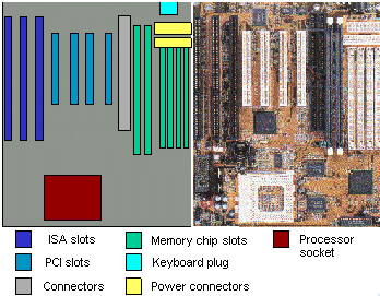
Here we see a diagram and a photo of a motherboard (or main circuit board).
This one is suitable for a Pentium CPU. Nothing has been plugged in or attached yet.

![]() Click on a part of the diagram or
on the matching photo and you'll be shown an explanation of that part below.
Click on a part of the diagram or
on the matching photo and you'll be shown an explanation of that part below.
![]() Show all explanations at once (good for printing)
Show all explanations at once (good for printing)
Explanation:
Keyboard
This is where the keyboard attaches, thru the back of the computer.
Power
This is where the power supply connects to the motherboard.
SIMM slots
Memory slotsThere are 4 short slots for SIMM memory.
This board has two long slots for a new kind of memory called DIMM DRAM.
This board can handle a maximum of 256 MB of memory.
From the manufacturer's description:
Two 168 pin DIMM DRAM slots (8/16/32/64 MB module)
Four 72 pin SIMM memory slots (4/8/16/32/64 MB module)
Supports maximum 256 MB with Fast Page/EDO/SDRAM DRAM
That's pretty scary stuff. Just keep such information handy for when someone who understands these things asks you about them.
PCI slots
This board has 4 slots for the newer PCI boards for peripherals like video cards, sound cards, internal modems, etc.
Connectors
Here is where cables connect to the motherboard for things like hard drives, floppy drives, and CD-ROM drives.
ISA slots
This board has 3 slots for the older ISA/VESA boards for things like video cards, sound cards, internal modems, etc.
Processor socket
What is visible here is the place where the processor plugs into the motherboard. When the processor is installed, you still can't see it because on top of it is a heat sink and fan to keep the processor cool. Hot processors make mistakes or even melt important parts on the chip.
Different processors are different sizes. So the socket on the motherboard has to match the processor. Also, the circuits in the motherboard itself must be different for different processors.
